Inside the CBM 8032 AV project
software and hardware development
The creation of the CBM 8032 AV performance required custom hardware development including the design and manufacturing of a small microcomputer, and writing software not only for the CBM computers but also for helper tools.
Basic System Architecture
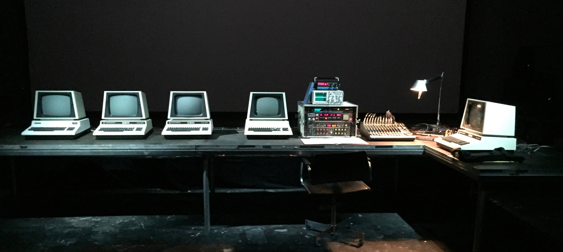
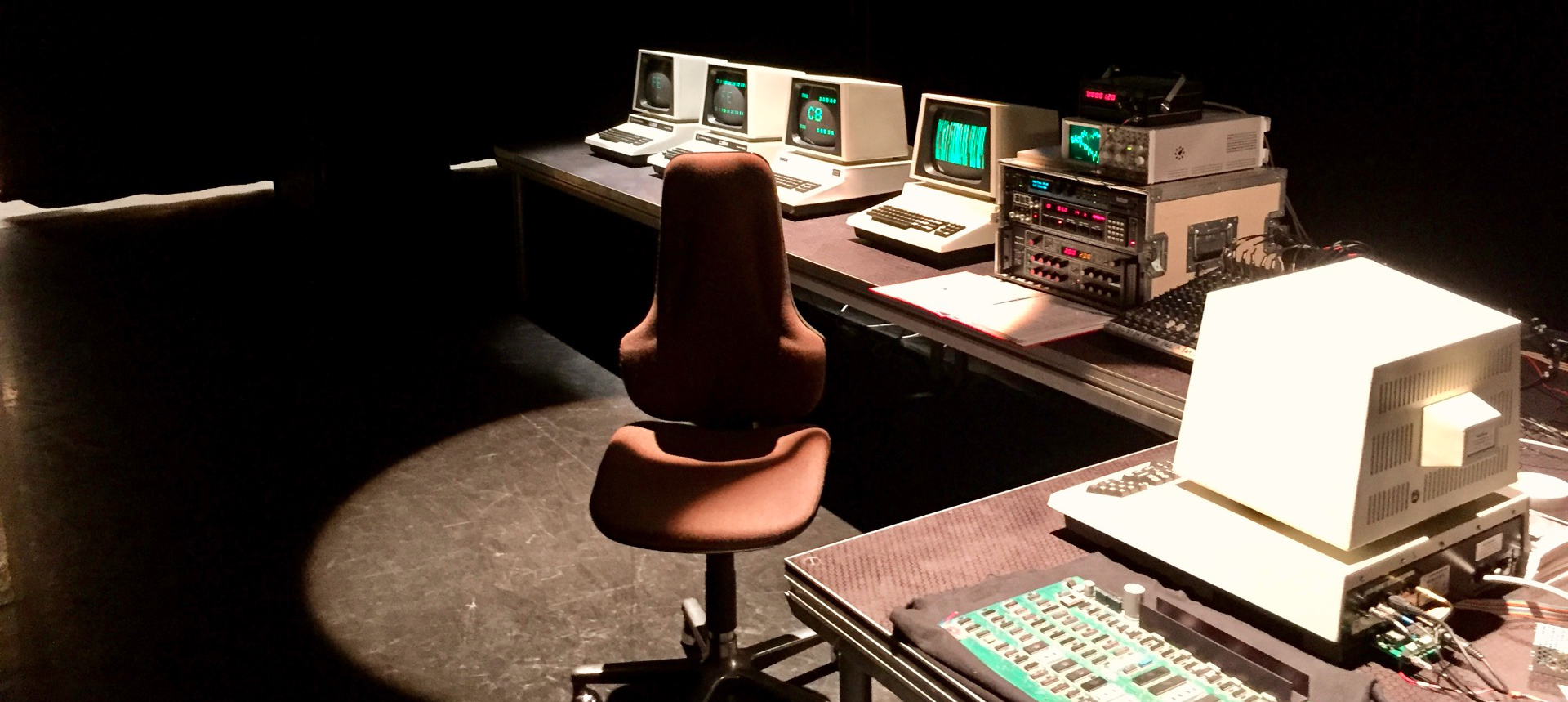
Due to the inherent technical limitations, an audiovisual performance using a single CBM 8032 computer would be too restricted. Hence, a network of several computers is used for the project. The stage setup consists of (photo above, from left to right) three CBM 8032 computers as sound generators for the music,
a single CBM 8032 computer as graphics generator, a rack with hardware audio effects, a mixing desk for the signals from the audio computers and the audio effects, a clock generator (a newly built computer, using the same microprocessor as the CBM 8032) and another CBM 8032 computer as sequencer,
controlling the audio and video computers as well as the clock generator. All computers including the clock generator are connected via a custom network.
Computer Network
The CBM 8032 computers don't offer the connectivity we take for granted now. There is no USB, or any other modern network. But there is the "User Port", an 8bit parallel I/O port on the back, and direct access to the NMI (see chapter about interrupts at the end of this page). With those two ingredients and a bit of custom hardware and software the sequencer computer is able to control the other computers during the performance.
Structure
The Clock Generator sends out a constant pulse of 32nd notes that drive the Sequencer. The Sequencer itself can recall a preset in the Clock Generator. That preset contains the tempo information and the swing settings. The Sequencer is a typical 'step-sequencer' with individual patterns for each Audio Computer and the Video Computer, organised in scenes. Recalling a preset in the Clock Generator or triggering a 'note' for the audio or video machines is done by first putting the corresponding data byte on the parallel bus and then sending an interrupt signal to the NMI line of the receiving computer, which makes that machine grab the data and raising a 'new event' flag.
Protocol
Each 'note' is represented by a single byte. Hence the audio computer could in theory play one of 256 sounds, and the video generator could do the same visually. However, the protocol is a bit more complex. The last four bytes (FC,FD,FE,FF) are reserved for special functions, like muting the currently playing note on the audio machine or clearing the screen on the video computer. Also, several audio routines have their own complex behaviour that depends on the order of notes events received, to allow for more compositional complexity. The video routines even more embrace that concept, where often notes are not replacing an image but modifying what is already there.
Hardware
The physical network consists of one 'Bus Output board' on the back of the sequencer computer, and a 'Bus Input board' on each of the audio and video computers. All machines and the Clock Generator are connected with a flat ribbon cable, transmitting the 8bit parallel data and the interrupt signals. The interrupts are generated by an additional parallel port added to the Sequencer computer. (for details see the DAC and Video board hardware chapter).
The Bus Output board also contains hardware that allows to connect a modern computer to the network during the development process. This is done via an Arduino Teensy board, controlled by a Max patch.
Hardware Extensions
When the CBM 8032 was released, the idea of extending it with additional hardware was part of its design. This concept of a 100% open and expandable computer system did not survive very long, it soon got replaced by very closed-off machines: The Apple II computer had five extension slots, was very well documented and could be opened easily. The Macintosh computer a few years later could only be accessed with a special tool, and Apple did everything to keep people from modifying it. The CBM 8032 in contrast can be opened using two screws and it offers an internal connector on the motherboard providing all signals needed to enhance and expand its functionality. Without that open architecture, the CBM 8032 AV performance would not be possible.
The hardware extensions we built are using circuits available already in 1980, such as the SN74LSxxx, or CD40xx series. The only exception is the video mirroring, which was not possible like this in 1980. But at that time, the idea to remap the characters for a 1920pixel x 1080pixel video output on a 15.000 ANSI Lumen projector would have been straight out of a science fiction movie anyway.
Video Out
Both the Sequencer and the dedicated Video computer have the ability to send out its internal display data to an external modern computer (Intel NUC running a Rust based application under Ubuntu) which reconstructs the image for the purpose of displaying it on a contemporary video projector. Capturing the video data is done with a dedicated video capture board inside the CBM 8032 computers. That board also contains hardware providing 8 more digital outputs, which are used by the sequencer to distribute the interrupts, and also provides an audio accent output which is controlling an analoge VCA.
Audio Out
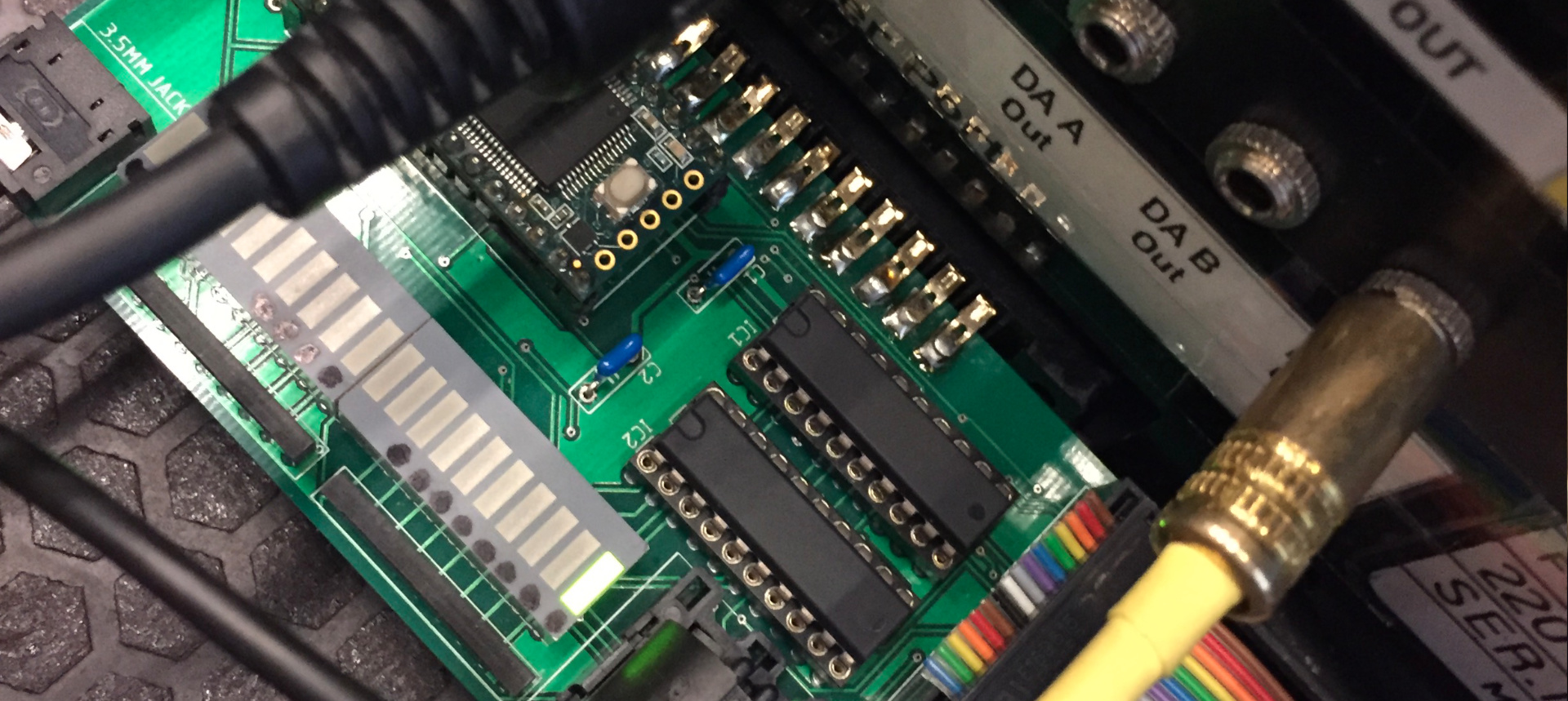
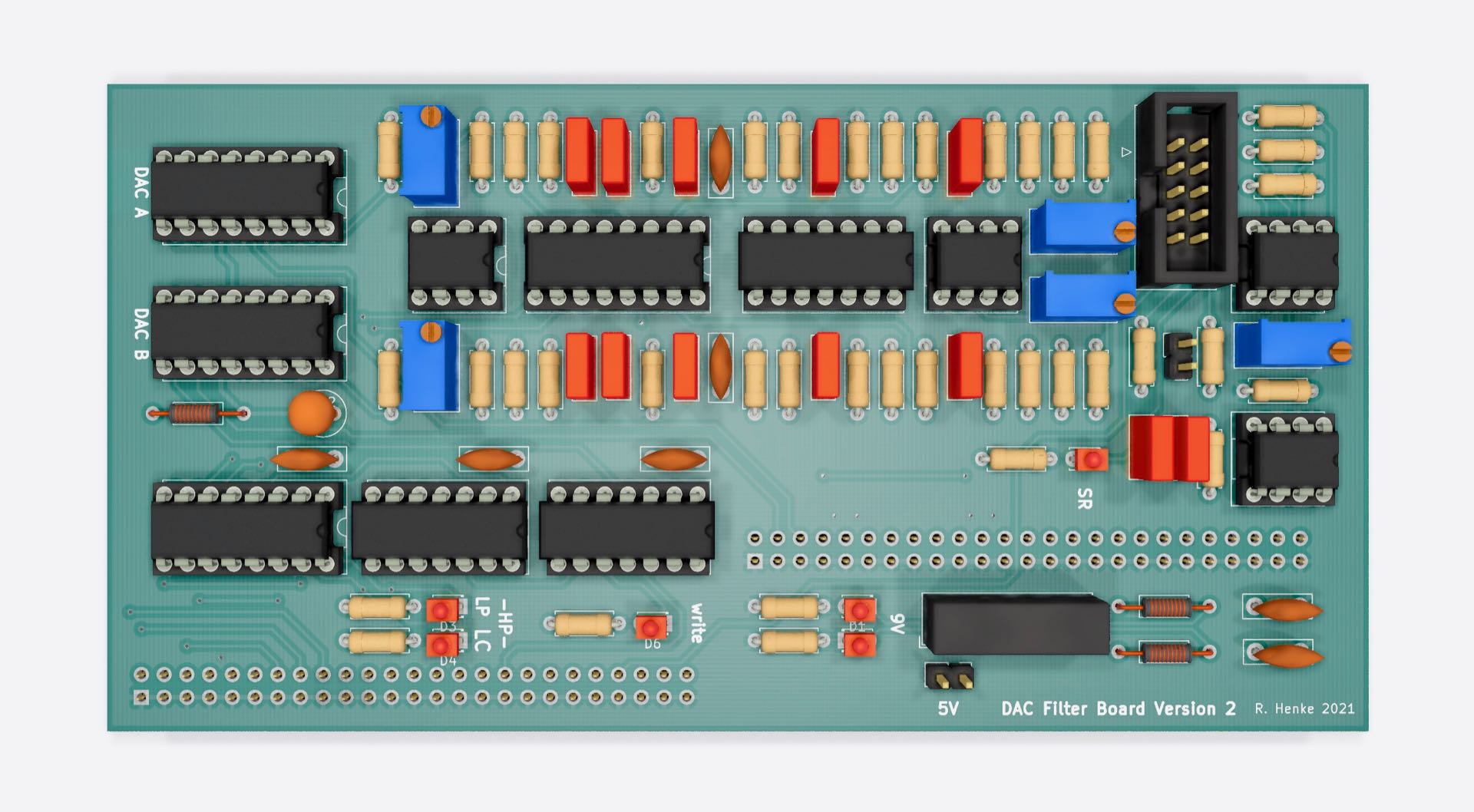
Each Audio Computer has dedicated additional hardware which consists of two 8bit digital to analog converters (DACs), basic fixed frequency filtering (thru, low-pass, high-pass) and gain settings (4 levels), which can be software controlled. This is not the same as a 'sound card' or as the legendary C-64 SID ('Sound Interface Device') chip. Those later extensions were capable of generating sound by themselves once receiving the right commands. Our DACs require the CPU itself to constantly calculate the audio waveforms.
Image above shows the 2020 (second iteration) version of the DAC and filter board inside the audio 8032 computers.
Clock Generator
The Sequencer needs an external trigger signal to advance a step. This signal has been created with various devices in the evolution of the project, until the current solution has been developed:
A small computer system similar to the CBM 8032 machines, utilising a more modern version of its original '6502' CPU runs a dedicated clock generation software. Since it is a full computer system it can also do other things in the future, such as sound generation. More information about this computer can be found on this page.
Video Generation
The CBM 8032's graphic capabilities are limited: A monochromatic green cathode ray tube ('CRT') display is driven by a simple display chip. The screen is defined as 25 lines with 80 characters, resulting in 2000 characters overall. Each character is represented as a single byte, using Commodore's PetSCII format. When a computer program wants to access the screen, it simply writes a byte representing one of the characters into a specific memory location. With each character being defined as 8 pixel x 8 pixel bitmap, the overall resolution is 640 x 200 pixels, although there is no way to control a single pixel. There is no native 'high resolution' graphics mode on these machines.
Character Sets
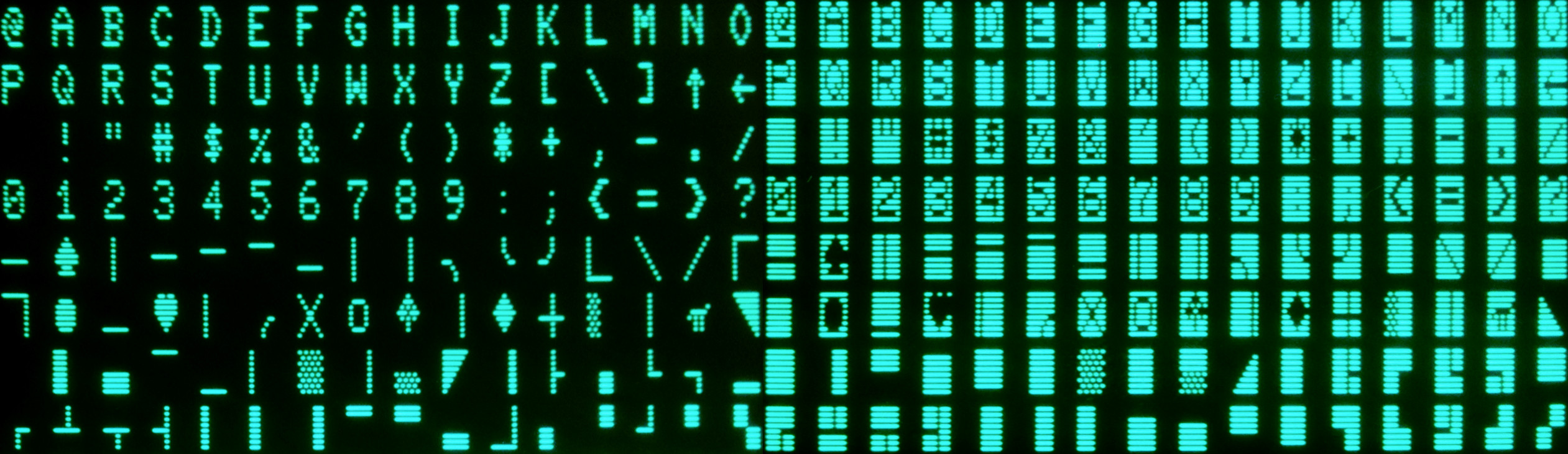
Two different sets of characters are available, one for text with upper case and lower case letters plus some additional symbols, and one for graphics, with only upper case letters and more symbols instead. The image above shows the available characters in graphics mode.
The screen is refreshed 50 or 60 times per second (EU / US models), but writing to screen memory itself is not synchronised with that process. However, that refresh rate is also causing a software interrupt, which can be used for graphic routines that benefit from a sync with the screen update rate, such as scrolling.
Drawing Algorithms
There are only 256 characters to choose from, of which half are unique and the other half are their inverses, The CBM 8032 AV graphics algorithms often only use a very small substet of those. The focus is on finding ways to make simple things interesting, and on the development of visual structures in time.
Each musical piece of the CBM 8032 AV performance utilises its own graphics algorithm, focusing on one set of shapes or movements. Within each algorithm, different incoming notes modify the behaviour of that specific algorithm. Hence simply sending notes in varying order or speed is enough to create complex evolving moving graphics.
Synced Drawing
The CBM 8032 computer uses the frame sync pulse from the display chip to create an interrupt. This interrupt is used by the system for scanning the computer keyboard. But users can redirect it to call other routines instead. We use it especially for scrolling (parts of) the screen content, or for the creation or deletion of shapes. By doing this, very smooth movements can be achieved, resulting in a feeling of speed and processing power way higher than what is actually there.
Video Projector Output
The CBM 8032 only provides a rudimentary video output, not compatible with any contemporary video format. We discussed several methods of getting the images shown on the computer's green cathode ray tube display out in a way suitable for a large video projection. Filming the display with a camera would not look good enough. Using a software emulator for the video computer would defeat the purpose of the project and would still not look good. Analogue to digital scan converters have their own artefacts which are beyond our control and we did not find a satisfying solution. We finally decided to throw a lot of contemporary technology on that problem.
Capturing Video Data
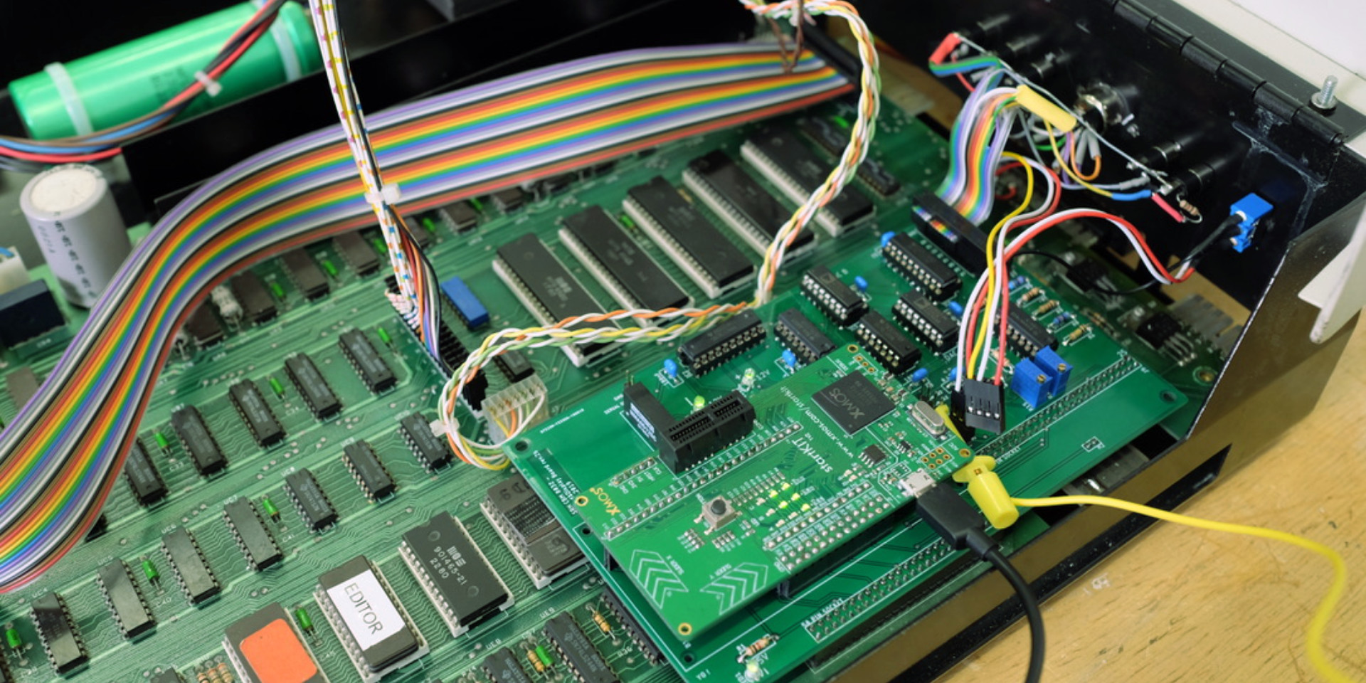
We use a high speed embedded CPU from XMOS to monitor the data bus, the address bus, the read/write line, and several other signals to gather the screen data when it is created.
This is greatly simplified by the fact that the CBM 8032 provides all necessary signals directly on its mainboard on two large pin headers for potential expansion boards. The XMOS CPU sends out a synchronised stream of data via its serial output, containing the current state of the CRT display data, 50 times per second.
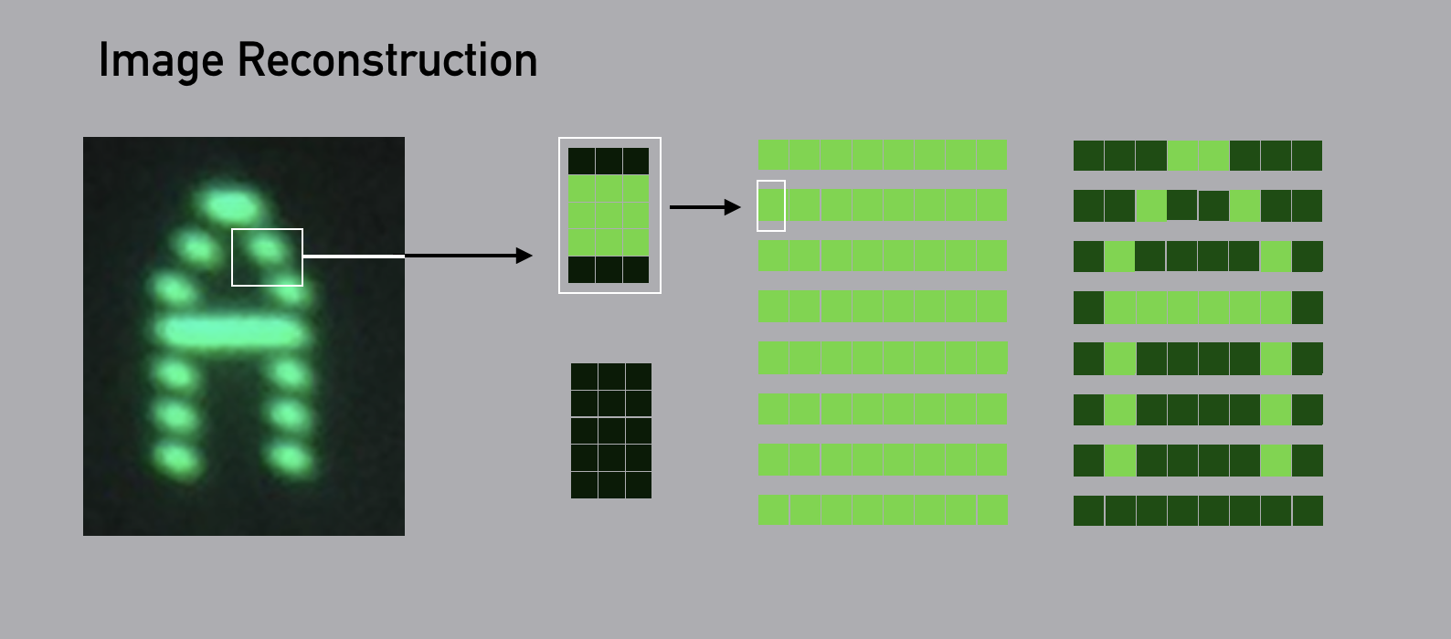
Rendering Characters
The video computer and the sequencer computer both contain the XMOS board. A simple switch allows to project either signal during the performance. To turn the serial signal into an image again, an Intel NUC computer running a Rust application reconstructs the characters including the typical phosphor decay behaviour and provides the HDMI output with 1920 x 1080 pixels.
The phosphor decay is responsible for the typical afterglow of the old CRT displays. Its behaviour is quite nonlinear, with a very rapid loss of energy right after the excitation and a very long low intensity fade afterwards.
Limits
The character reconstruction is not 100% perfect. In some cases the drawing algorithm creates characters much faster than the refresh rate of the screen, and this refresh is a continuous process starting from the top left, going line by line down to the right bottom. In that case, for a single frame, some 'hybrid' characters might occur that are a combination of the upper half of one character and the lower one of a different one. Ironically, to reproduce this behaviour exactly would require an even more powerful contemporary CPU, and we decided against it. [A problem similar to the attempt to perfectly reproduce the behaviour of early digital synthesisers in software.] However, in most cases the difference is acceptable.
Aspect Ratio
The original Commodore 'Pet 2001' and the CBM 40xx models had 1kByte screen memory, and were capable of displaying 25 lines with 40 characters each. That produced a nice character aspect ratio and especially the graphical symbols did benefit a lot from it. After all, they were designed with this geometry in mind. The CBM 8032 offers twice the screen memory, it displays 80 characters per line. The characters are now drawn much narrower, which does not nearly look as good.
To project the characters in full HD via a contemporary projector we had to rescale them anyway, and decided in favour of a more appealing compromise for the aspect ratio, which is somehow in the middle between the CBM 40xx and the CBM 80xx models:
The result is basically a CBM 8032 'widescreen'. Each pixel of the original characters is represented as 5px high and 3px wide object, leading to a resolution of 80 x 8 x 3 = 1920 pixel horizontally and 25 x 8 x 5 = 1000 pixel vertically.
For 1080p compatibility we leave the first and last 40 screen lines black.
Vertical CBM pixels contain three green HD pixels, in between two dark ones, emulating the typical horizontal CRT line drawing effect.
Sound Generation
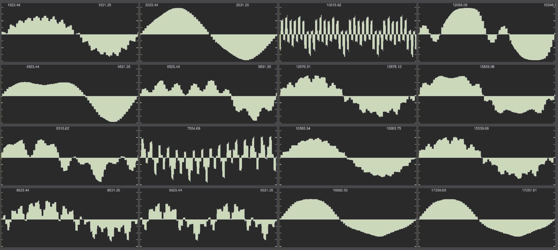
The image above shows a set of waveforms produced by a wavetable generator algorithm.
The CBM 8032 has no dedicated sound chip, unlike later Commodore computers including the C-64 with its legendary MOS 6581 / SID ("Sound Interface Device). However, the motherboard does contain a MOS 6522. This Versatile Interface Adapter chip ('VIA') provides not only the 8bit data lines for the User Port, but amongst many other things also contains a shift register. This is used by the hardware to drive a piezo speaker for the startup sound. Some audio routines for CBM 8032 AV also utilise this method. A more powerful and flexible way of sound generation can be achieved by adding digital to analog converters ('DACs') to the system.
Here is a dedicated page with a detailed breakdown of one of the sound routines:
8bit kick drum synthesis
.
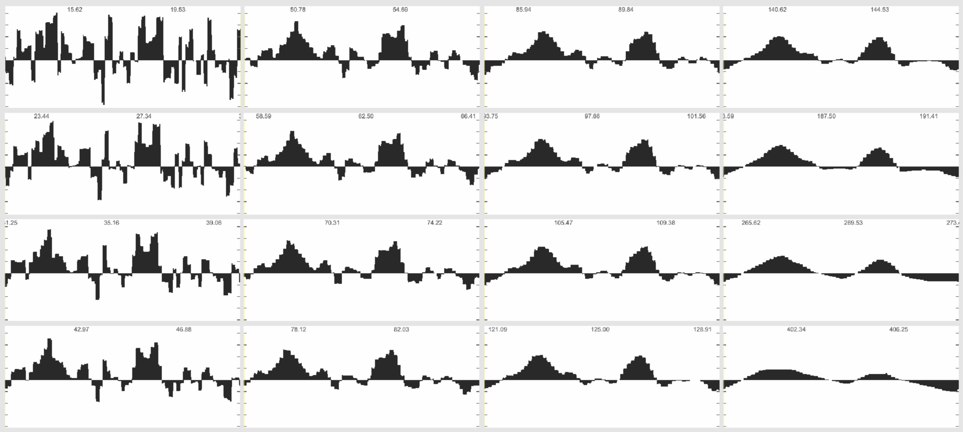
Image above: Karplus-Strong physical modelling synthesis. Image below: Band limited random noise modulation of VIA 6522 shift register output.
Shift Register
The 8bit shift register of the 6522 VIA chip can be set in a state where it functions as a signal generator, rotating its content at a rate defined by an internal register, as a fraction of the CPU clock. Since the output is a 8 bit binary pattern, and the frequency is set using a single 8bit register, the resulting timbres are not very complex unless constantly modulated, and the pitches can only be very roughly tuned to musical intervals. But since both the actual pattern in the shift register and the clock division can be set very fast by simply writing values in two control registers, a surprising range of interesting (noisy) timbres and 1bit waveforms can be achieved, as long as the goal is not equal tempered musical note pitches, which are impossible due to the low CPU clock speed. The output of the 6522 is sent out to the mixing desk without any filtering.
DACs
Two additional linear 8bit digital to analog converters ('DAC') have been added internally. They can be updated by sending a byte to their physical memory address. It is possible to send a value to both DACs or only to the left or to the right channel. We make use of this in some stereo sound generators. Creating sound using the DACs means that the CPU must provide a steady stream of data, at pretty high rates. Due to the 1MHz clock of the 6502 CPU, every clock cycle counts, and sound generation routines must be extremely simple. We rely a lot on usage of tables, there is no such thing as floating point numbers, or even multiplications. The built-in random number generator routine in the ROM of the CBM 8032 needs a few hundred CPU cycles for each call. This is too slow for creating audio noise. We wrote a simpler version that only needs 75 cycles, allowing us to create noise with a bandwidth of 10kHz.
Filter
The low resolution sounds from the DACs updated at low sample rates sound unique and the artefacts create rich overtones. However, for some timbres it is beneficial to tame that sound by applying mild filtering. The DAC boards provide three filters which can be set from within a sound routine: a lowpass, used for some bass drums, a low cut used for snares and other sounds that do not need very low end, and a high pass that is beneficial for hi-hats. And of course a bypass. The aim of the filters is to keep the timbres but slightly clean up the mix. Their effect is subtle and not comparable to a classic synthesizer filter.
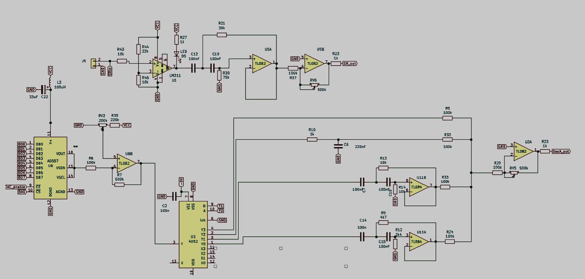
Image below shows schematics from DAC board revision 2 with its output processing of the shift register (LM 311, TL 082), a DAC channel (AD 577, TL 082), the filter input switching (CD 4052) and the filters (TL 084, TL 082).
The two sound generation methods both have their merits and issues. Whilst the build-in shift register is extremely limited, it only needs to be set to a specific value once in order to start producing a rectangular signal until turned off, thus the CPU is free to do other things whilst there is still sound.
We make use of this on the video computer, where some visual routines also set the frequency of the clock division when drawing characters on screen, providing a highly synchronised audiovisual experience for almost no additional CPU cost.
The DACs in contrast requires the CPU to constantly calculate the output without any interruption: Whilst sound is running, not even drawing anything on screen is possible.
However, the possible sonic palette is much larger, low resolution sine waves, sounds with decaying volume, and quite perfect musical pitches over a large octave range are possible. Most sounds of the CBM 8032 AV project are using this method.
Audio Processing and Mixing
By using multiple computers for sound we can create up to three simultaneous voices, each either using the DACs or the shift register output. With the addition of reverb, pitch shifting and the ability to freeze / loop some material, sufficient sonic and musical complexity can be achieved.
Mixing
The three audio computers each provide a mono output from the shift register and a stereo output from the two DACs. The sequencer and the video computer also provide an output from the shift registers. Sequencer emits a short beep when changing scenes, which adds additional structure to the music. Some video routines also emit highly synchronised sound via the shift register. Effects are integrated using sends and input channels as returns. Filtering all the signals using the mixer EQ is also an essential part of the musical performance.
Scan below shows the track sheet for each piece, with mixer settings, effect settings, and pattern/scene numbers. These settings have to be changed manually during the performance. After touring with this project for several years, I am not looking at them anymore, but change things 'on the fly' when playing.
Pitch Shifting
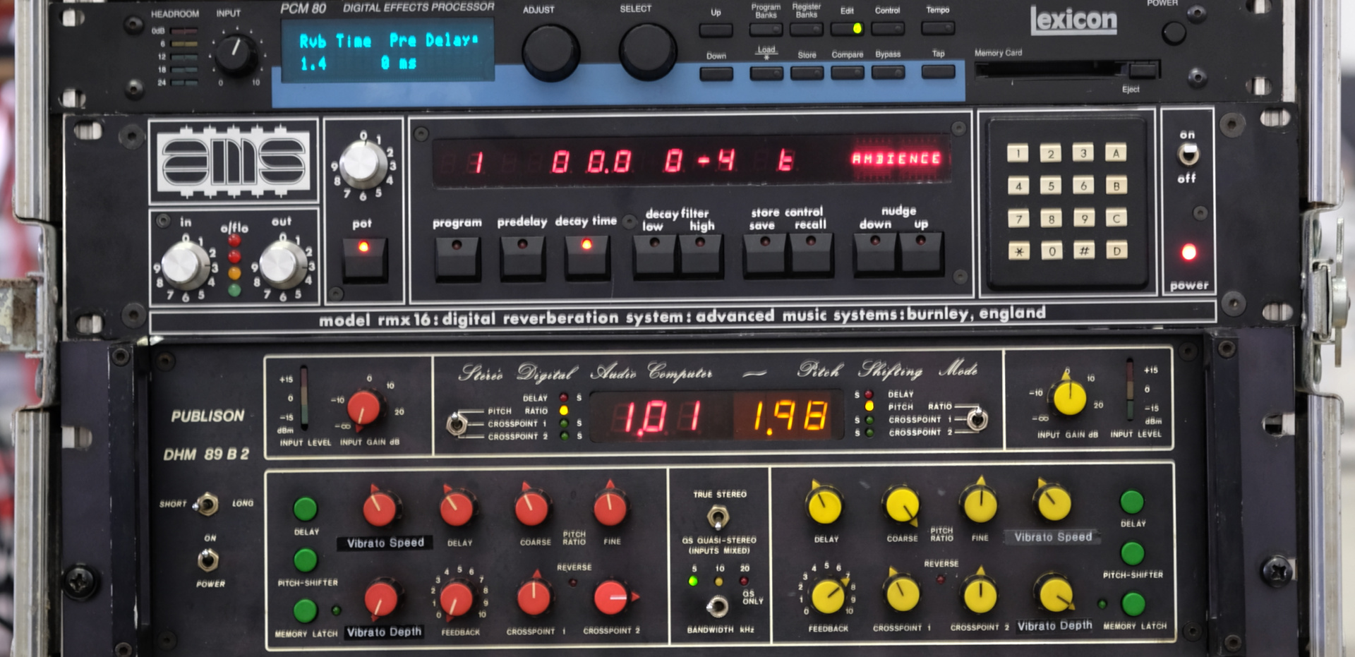
The Publison DHM 89-B2 from 1978 is a dual channel pitch shifter that can work with unusually long buffers (up to 5 seconds) and has a freeze function, which keeps the current input signal circulating in the buffers and still allows to re-pitch them. In combination with the PCM 80 complex feedbacks between pitch shifting and reverb can be created, that allow to turn a momentary signal into a sustained tuned drone, adding additional harmonic layers. The DHM 89-B2 has no presets, adjusting the parameters can only happen with analogue controls on the front panel, leading to all sorts of happy accidents and unpredictable behaviours.
In late 2022 the Publison unit had become too fragile for touring, and has been replaced by the PitchLoop89 remote.
Reverb
The raw sound from the computers benefit a lot from adding reverb, provided by a Neve AMS-RMX16 effects unit from 1982 and a Lexicon PCM 80. Which is a bit too modern, but the more fitting Lexicon 200 we don't have. The RMX 16 mainly provides short reverbs, chorusing or nonlinear / sparse effects, whilst the Lexicon does the classic long singing reverb tails especially suitable for tonal signals.
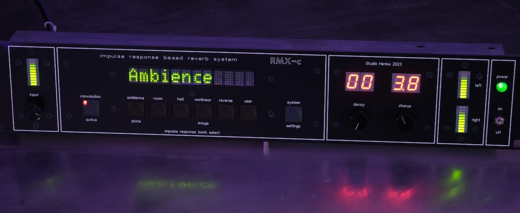
In mid 2023 the AMS-RMX16 unit had become too fragile for touring, and has been replaced by the RMX-c convolution engine shown in photo above.
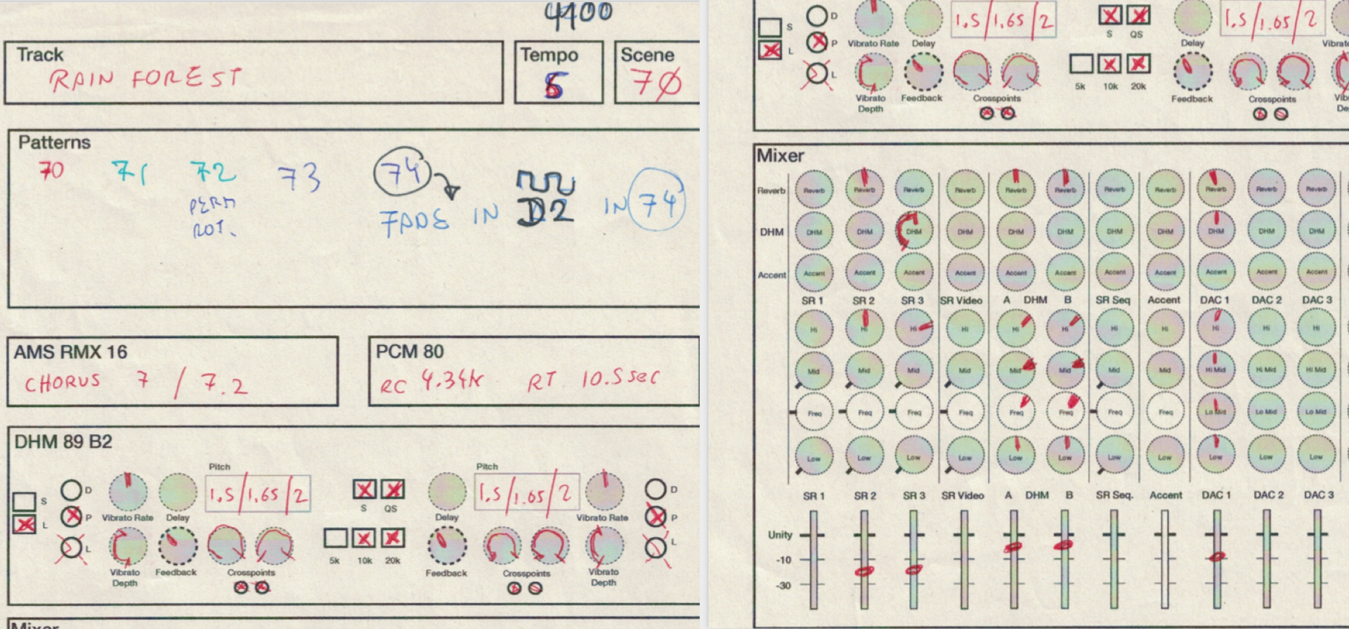
Photo below shows the original effect rack, used from 2019 till late 2022, still containing the Publison DHM89B and the AMS-RMX16.
Sequencing
The sequencer written for this project follows a classic pattern-based approach: It provides five tracks, one to control the video computer, three for the audio machines and one generating the accent signal for audio processing.
The sequencer is driven by a clock signal in 32nd note intervals, provided by an external clock generator. Each pattern consists of up to 32 steps, advancing by 32nd ,16th, 8th, 4th... etc. note intervals. When switching from one pattern to another, that process is quantised to one bar. The sequencer also has an offset parameter, and there is an option to play back steps in random order.
Data Entry
The data for each step is represented as a two digit hexadecimal number, allowing for a theoretical maximum of 256 possible 'notes' per track. Some notes have specific functions, like representing no note at all (FF), or silence (FE), or mute track (FD), which effectively turns the currently recalled pattern into a one shot.
Settings for all currently running patterns can be stored in a scene. This allows to recall parts of musical pieces in a timed manner and makes it possible to create fluent rhythmical transitions between parts. When a scene is recalled, the Clock Generator receives its number and recalls the associated tempo and swing data.
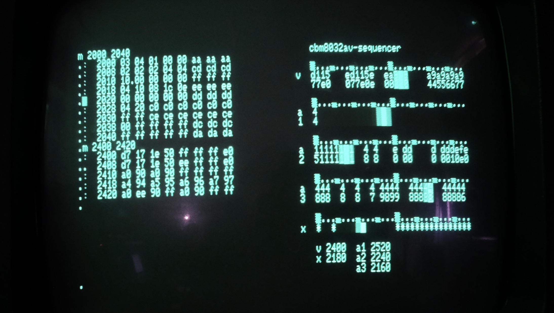
Pattern Display
The right side of the computer screen represents an overview of the currently running patterns for all tracks, including the memory locations containing the actual data in these patterns.
To avoid the significant effort of developing a complete user interface for the sequencer, and not just a display as in the current version, editing pattern data happens using the hex monitor provided by the CBM 8032 operating system, shown on the left side. Changing a sequence literally means writing directly into the correct RAM addresses.
That might perhaps be changed in a later version of the sequencer code.
Keyboard Control
The performance is organised in ten pieces, each with dedicated memory locations in the sequencer. Each piece can consist of up to 16 scenes, and each track can have up to 8 different patterns. The limiting factor here is the available amount of RAM in the sequencer computer.
It is possible to mute tracks, and to stop the sequencer and restart all patterns in sync. For this purpose the numerical keys on the computer keyboard are utilised. There is also a function to reset pattern positions every x bars, which is important when creating patterns with uneven lengths. Pattern data also can be copied from one location to another, either in the same or any other track.
Clock Generator: Firebird 6502
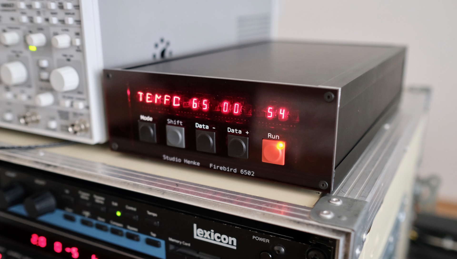
The sequencer needs to be driven by an external clock. In the first iteration of the project this clock was provided by a modular synthesiser VCO and a clock divider circuit. This solution was too imprecise. In Summer 2021 it finally got replaced by a 6502 based microcomputer, I developed specifically for that task, named Firebird. This solution allows the sequencer to communicate with the clock. Whenever the sequencer recalls a scene, the clock can change its tempo and swing behaviour.
Development Tools
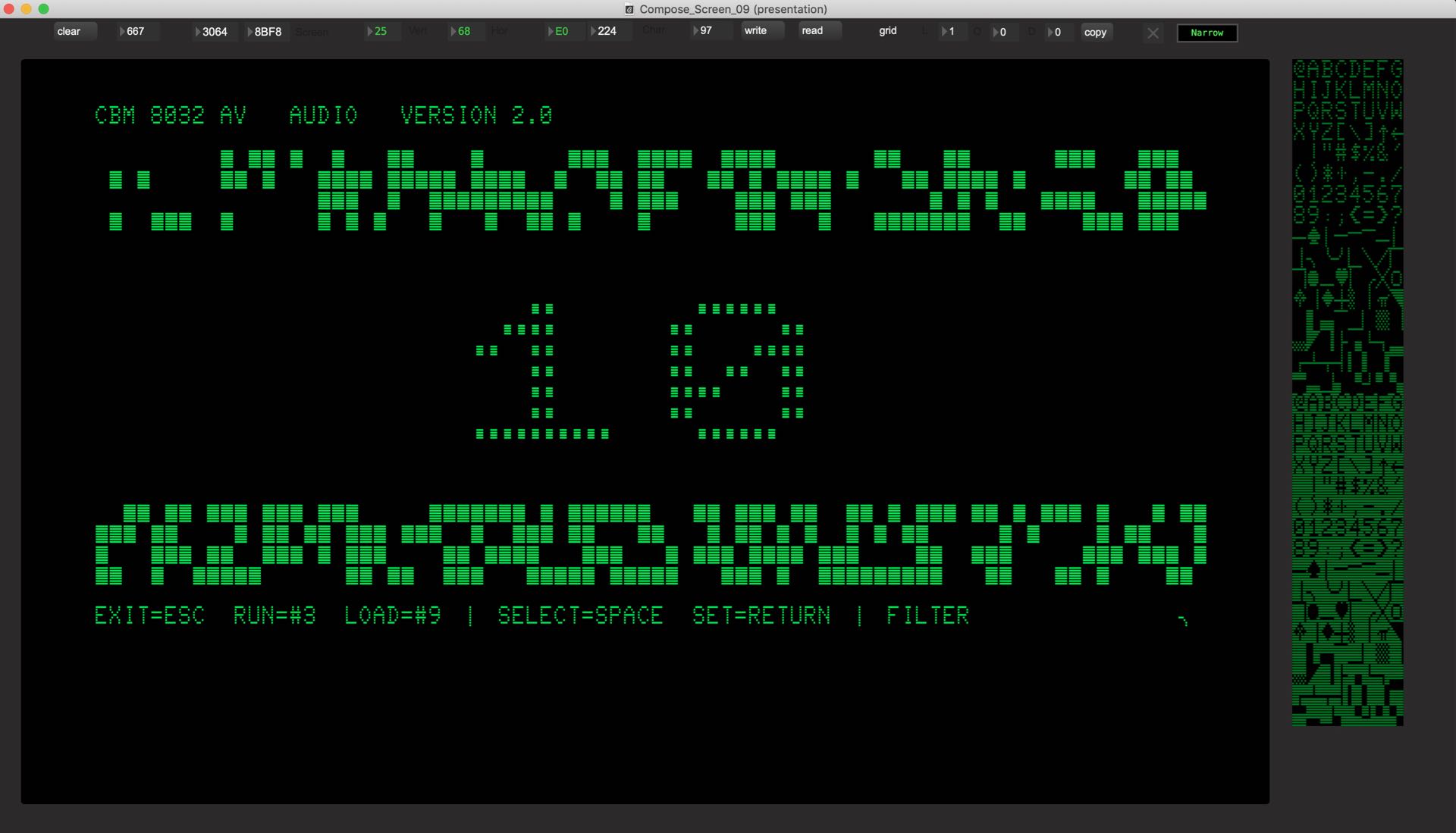
The image above shows a graphics editor that helps to envision how graphics and UI setups will look once becoming real.
The CBM 8032 AV project started very naive in early 2016. It grew in complexity and did require the development of unique workflows and tools. A lot of Max patches for various tasks have been coded, spreadsheets with memory / routine locations had to be created and maintained, hardware extensions made it necessary to become familiar with PCB layout software, and we ran many simulations of audio- and visual- routines before actually coding them.
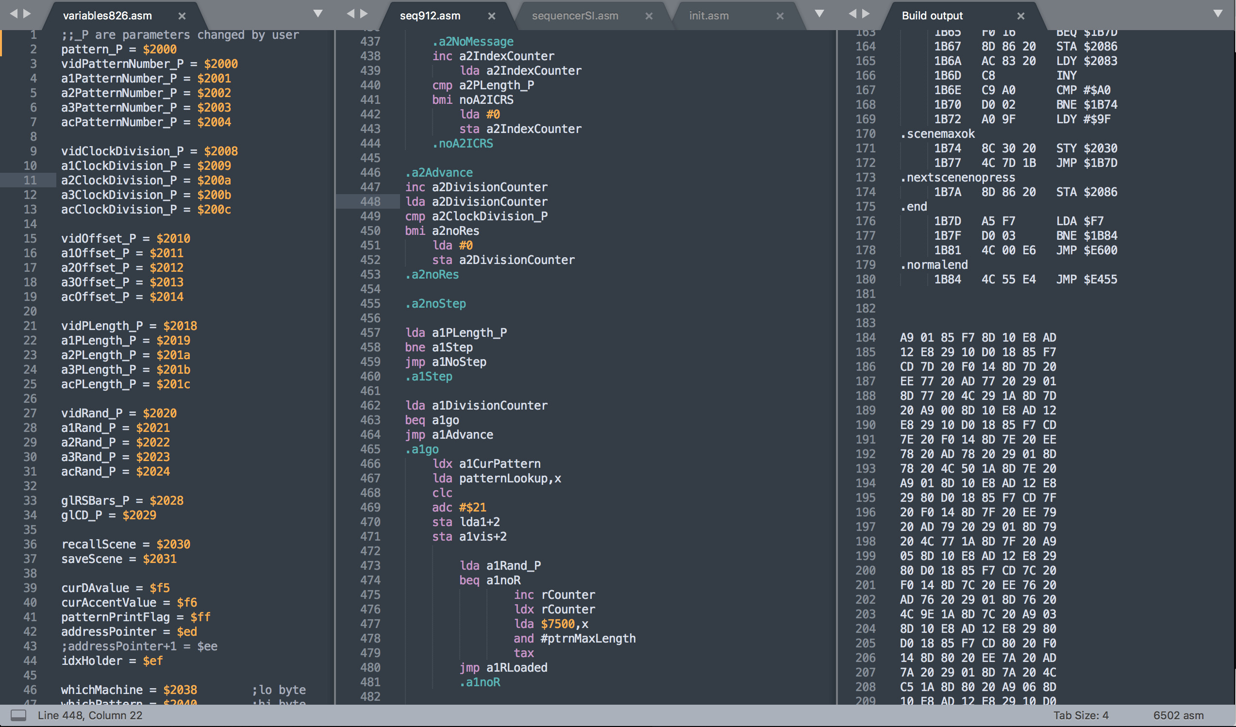
Assembler Tools
At the beginning, I wrote assembler by hand on paper. Then I started using an online assembler program and wrote an early version of the Max based file transfer program. Once we became a team working on the project, we decided things need to operate on a different level, and we started using a 6502 assembler extension for the Sublime editor and I moved the code to Github. That turned the project into a serious software development adventure.
Each CBM 8032 computer is equipped with an internal SD card floppy emulator, a PetSD+ unit. Whilst this is helpful for storing final data and utility routines, it is not suitable for fast data transfer during development.
Data Storage and Transfer
Assembler routines and tables are created externally. We use a Max patch in combination with an Arduino Teensy to send data to the CBM computers via their User Port.
On the receiving side, a short assembler routine is receiving the data. This turned out to be a relatively fast and very reliable method. It also allows to quickly update selected memory locations without the need to reload the complete data. The lack of 'protected memory' has its merrits...
Growing Complexity
What started as a simple Max patch to transfer programs matured into a Swiss knife. It now contains a generator for various waveforms needed for audio routines, a comprehensive hexadecimal-decimal-binary converter, a sequencer with realtime input for fast testing of new sound generation routines, and a text-to-PetASCII tool.
Interrupts and Timing
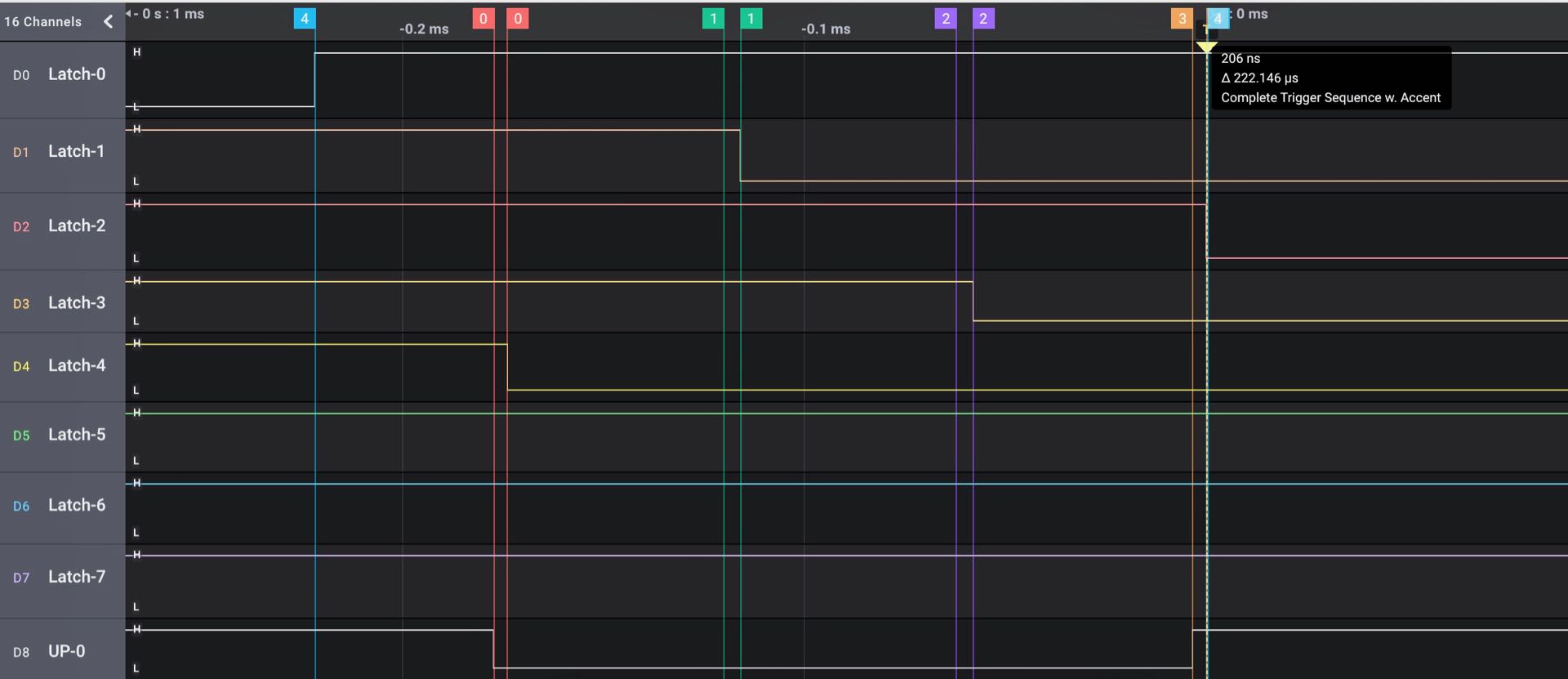
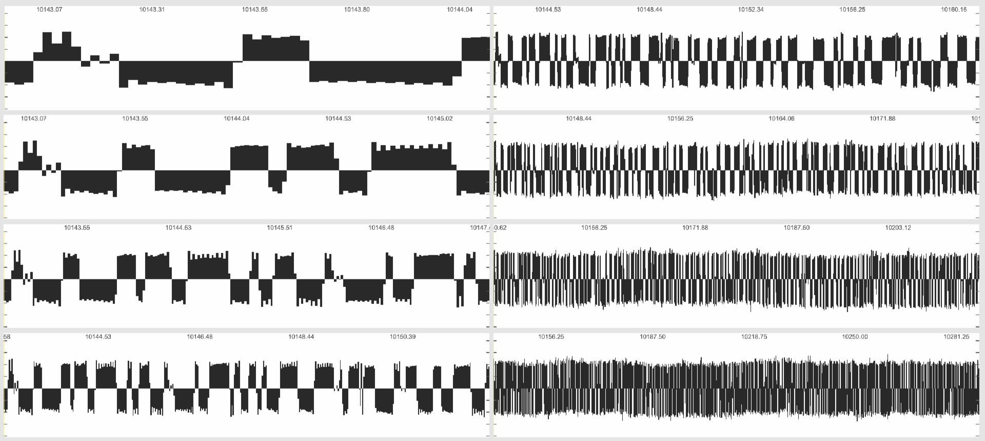
Screen capture above shows sequencer output sequence.
When we started the project we were very naive. We coded some 'proof of concept' sound and video routines in assembler, and that gave us the confidence to move on. We later had to learn that things are much more complex. A lot of it has to do with the handling of time. The CBM 8032 is a basic single CPU system. Its CPU can do one thing at a time, step by step. Already early in computer history it became clear that this method has its limits, especially when a computer program needs to react to any external input, like getting key presses: The CPU has to scan the keyboard in regular intervals, and if the main program is long and complex that would imply it has to jump again and again into a keyboard scanning routine from multiple points in the software.
If the program has to react to multiple inputs that need to be observed, this method becomes impractical. The solution is the concept of the 'interrupt' which is an external signal to the CPU, that can at arrive any time, and tells it to stop what ever it is doing, and execute the code of an 'interrupt handler routine' before jumping back to where it was before. Using interrupts is the key to any realtime system such as ours.
6502 interrupts
The 6502 CPU offers two types of interrupts, a 'regular' IRQ, which is triggered by multiple sources including the keyboard and floppy ports, and which can be disabled in software, and the NMI, which has highest priority, cannot be disabled, and is normally not in use in the CBM 8032.
The sequencer engine receives its clock pulses as NMI, and the interrupt routine does all the calculations necessary to send the current step data to the four other computers. Once this is done, it updates the graphical display to reflect the current state.
The timing of this routine depends on the number of CPU cycles necessary to execute the code. This might depend on several states; resetting several values at the end of a bar takes a bit longer, or resuming after stop. However, the derivations in timing are in the range of a few microseconds, ten to hundred times better than what MIDI via a 5pin DIN cable offers.
On the sequencer computer, the software interrupt (IRQ) is not disabled, because it is important to scan the keyboard and serve the hex monitor routine. Since the NMI has priority this does not affect timing.
receiving notes
On the receiving side, things are more complex. To create a sine wave using the DACs, the program has to loop through a sine wave lookup table in a complete regular fashion. The standard software interrupt which happens every 20ms and is triggered from the CRT controller would interfere with this, and has to be disabled. (This implies we have to build our own key scanning routine if we want to e.g. react to an "esc" command to exit the software, since the key scanning of the OS is not called anymore).
When an NMI arrives, it indicates that the User Port has valid 'note' data, defining which sound routine to play next. The interrupt handler cannot simply abort the current playing routine, but rather raises a flag indicating that a new note arrived.Each sound routine has to check that flag in regular intervals. This process takes almost no time ( < 10 CPU cycles / 10 microseconds ) and can be done very often without causing problems.
If the flag is raised, the currently playing note routine exits to a global note handler routine which looks up the desired new note, and uses a jump table to determine which sound to create next. This routine also resets the flag, and it is responsible for drawing the note number on screen, which takes 1.5ms. This implies a short moment of silence between notes, but the drawing is essential for the show.
timing and jitter
The less often a sound routine is checking the new note flag, the less accurate the timing would be. Practically, we do this at least every 100 cycles, giving us a timing accuracy of 0.1 milliseconds. Due to its simplicity, the sequencer timing of our 1980s system is exceeding MIDI hardware timing by a magnitude.
The audio computers draw a large number on the CRT display when a new note arrives. This is done in the interrupt handler and takes 1.5 milliseconds. Since this is happening for each arriving note, the delay is identical on all audio voices when they get notes at the same time.Running an audio routine which involves using the DACs requires a constant stream of data to them, and there is no CPU time left for also drawing things on screen. However, when a percussive note has finished, it jumps into a 'idle' loop, which scrolls two lines horizontally on the screen, providing an additional visual cue.
The concept of 'note' is also applied to the video computer, but the code operates differently. On the sound machines, a new sound will always terminate the currently playing one — the system is monophonic. In contrast, already running video routines are often just modified when a new note arrives, deleting or altering parts of the image or changing visual movements instead of starting from a blank screen. This is more complex to sequence: the order of arriving notes defines what happens to the image. 'Clear screen, draw square, rotate' obviously does not do the same as 'draw square, clear screen, rotate’.